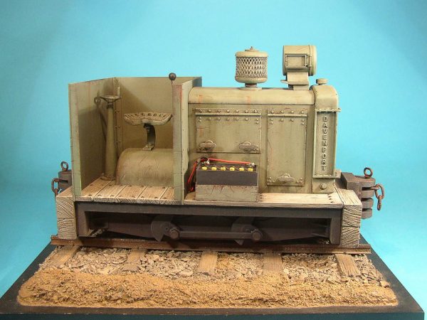
I didn’t jump on buying the Roundhouse Katie back a year ago. Rather today, I made a purchase of the 7/8″ scale Davenport made by Back to Bay 6 in the UK. I have been following the SE Lounge Forum rather religiously in the last couple of years and have always been impressed by the size and quality of the scale models presented there.
Seven Eighths scale (also written as 7/8″ scale or 1:13.7 scale) uses 45 mm G gauge track to represent 24 inch narrow gauge and so is a very popular scale for people modeling the Maine two-foot railroads (like the Sandy River and Rangeley Lakes, the Bridgton and Saco River, and the Monson Railroads) and the Welsh slate railways (the Ffestiniog , the Corris, and the Talyllyn Railways).
I don’t have too much invested in 1:20.3 rolling stock at the moment and several people have kitbashed Regner locomotives like my Konrad into 7/8″ scale. Here’s one example done by Chris Bird:
While surfing around the blog entries on the Model Railroad Hobbyist website, I came across a link to the Upper Canada and Algonquin Railway group, who were building an On30 modular layout based on the Free-Mo standard. Unlike other modular systems like Ntrak, Free-Mo sets some basic requirements, particularly around the module height and the module-to-module interface, and then lets the module designer a great deal of latitude on all other aspects. Prototype modelers have taken to the standard very quickly as it allows them to reproduce real track patterns very accurately. It also allows a lot more creativity removing the “slot-car” look of other older module systems.
I’ve always liked the Free-Mo concept especially now that I don’t have room for a full layout. I could build a couple of modules and participate when I’m around and store the modules away when I’m in the Netherlands. In addition, with Bachmann’s recent releases of On30 locomotives including Shays, Climaxes, 2-6-0’s, 2-8-0’s and 4-4-0’s, there are a lot of possibilities to mimic the Key Valley’s locomotive roster in On30.
The UC&A Railway ran out of steam after a few years but Ron Hurlbut has a webpage documenting its history.
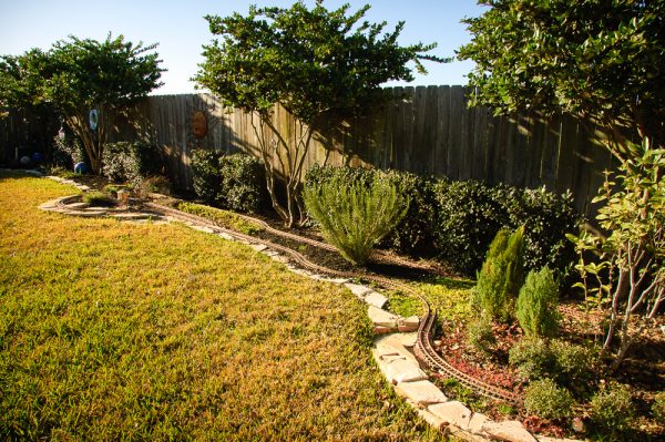
March 8: The first version of the Lost Hollow Railway has been decommissioned due to a job-related move. I still hope to make it out to the various steam-ups in the southeast Texas area over the next few months and rebuild the Lost Hollow Railway at our next place.
I learned many things on my first garden railway:
The hardiplank roadbed system I used worked great for the soil here in Houston. Everything was rock solid and I had no problems with track alignment. Thanks to John Frank for his advice in this area. Details on the hardiplank roadbed system are available here. My only issue was keeping the purely cosmetic ballast in place on top of the hardiplank.
I put ground zero too low. I should have raised it about 1-2″ more than I did. I had some problems with the lowest level terrain getting filled in with earth from higher points of the layout.
I should have built retaining walls between the the upper and lower mainlines at several key places. In the center section of the layout, even though the upper and lower mainlines were separated by only 3 inches in vertical height and about 9-12 inches horizontally, I had difficulties keeping the earth on the upper mainline from running down onto the lower mainline. A retaining wall or crib system would have helped.
Switches were mostly unnecessary for this live steam layout. The small radius Aristocraft ones that I used were probably too small anyways.
We should have put down a weed/plant barrier in the loop sections of the layout to get a handle on the weeds. The layout got very weedy in the last couple of years.
January 14: Not much to report in early ’07. I did have problem with the Konrad at a steamup just before Christmas; it failed to light properly. After ripping things apart, it looks like that there was something plugging the fuel valve.
April 28: I’ve finally resolved my firing issues on the Regner Konrad; turns out the screw joint between the brass jet fitting and the steel jet holder was leaking, which was causing poor fuel delivery to the burner. A little Teflon tape and I’m back in business! The garden has got away from me again and I’ve got some weeding and cutting back to do.
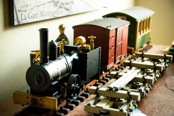
May 6: I purchased another rolling stock kit from Twin Mountain Model Works; this time, a plantation-style boxcar. It should look good at the end of the logging train or with Coach No. 2.
The Steamer Dock on the PM&TCoThe Mark I version of the PM&TCo. has been abandoned. It was a good starting layout but I found it difficult to progress on the layout over the last four years with our living arrangements in Texas. I hope to restart work on it when we get a place with a more appropriate space for a layout.
The next completed piece of rolling stock on the Lost Hollow Railway is a Twin Mountains Model Works plantation boxcar. Once again, the kit is well-thought out and definitely easier to put together than the coach.
January 1: For a change of pace, I started work today on kitbashing my Regner Konrad. Photo set available here: “Regner Konrad Kitbash“.
January 2: Robin and I worked on the garden today, replanting a lot of the plants we had to remove to clean up the old garden. New photos in this set: “Rebuilding the Garden“.
January 16: I’ve been traveling a lot over the last couple of weekends so no progress on the Lost Hollow. We had the first big storm to hit our area in a while; it will be interesting to see if any earth moves around.
January 17: Received in the mail today, two Hartford Product log disconnect kits. Finally, we will have some rolling stock for the Lost Hollow. Also came across this most excellent article on MyLargeScale.com on figure building: I’m going to have try to build a few at some point.
February 2: Regner has a new locomotive out, one that looks a lot more North American: the Lumber Jack. Very cool. Haven’t been around much, so the layout has not progressed much.
February 4: Spent a couple of hours ballasting the track this afternoon. The improvement of the look of the railway is tremendous: no more white hardi-plank showing through everywhere. Need to buy some more flagstone before the ballasting is finished though.
February 5: Took the opportunity to run Engine No. 1 around the layout this morning to check on the quality of my ballasting. Had to adjust things in a few places but all in all everything was good. Finished the ballasting on all but the front section in the afternoon.
February 9: Despite having the two Hartford Product kits to work on this week, I spent the last couple of evenings building a scale figure. I’m pretty pleased with my first attempt.
February 10: I bit the bullet and disassembled Konrad today for repainting. I’m using Krylon semi-flat black to cover the orange and dark green on the outer surfaces. I also drilled and tapped holes for the new hex nuts to hold the rear coupler on. Now I just need to put it all back together properly!
February 11: Konrad is all back together. See the photo set available here: Regner Konrad Kitbash“.
February 21: Came across the Twin Mountain Model Works website yesterday. The small coach would be perfect for the Lost Hollow Railway.
March 11: Spring is coming to Houston so things are starting to grow rapidly in the garden. I’m clearly going to have to spend more time weeding over the next few months. I also ordered a coach kit from Twin Mountain Model Works. This now makes three kits I need to finish.
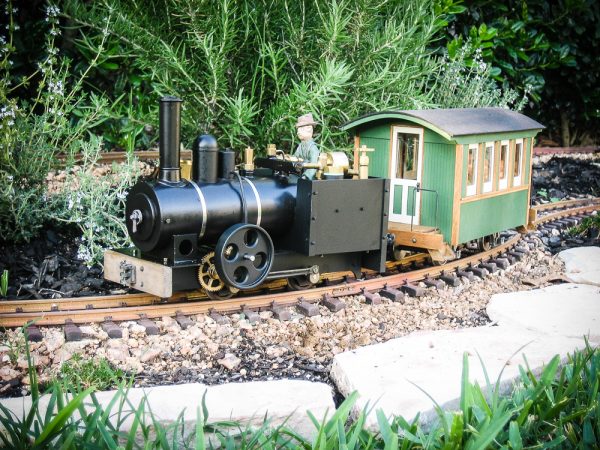
April 9: I got started on the Twin Mountains coach. The colour scheme will be Polly-S coach green with Polly-S beige highlights and Floquil maple stain everywhere else.
April 20: The coach is finished, which means I have finally have something to pull at the next steamup.
April 29: John Frank hosted the Spring 2006 Katy Steamup today. A photo set is available here.
May 20: Robin and I moved some more plants around and I reballasted a good portion of the line. This time I screened the decomposed granite ballast and used only 1/4″-minus material. I also harvested a good load of oregano, thyme and rosemary.
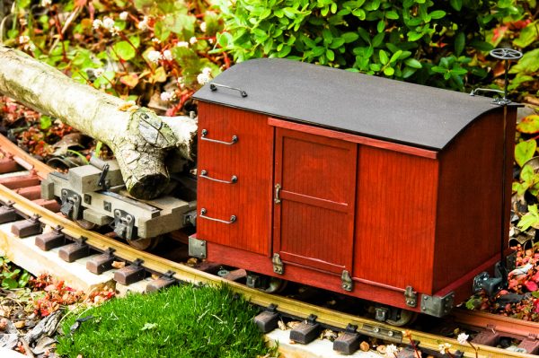
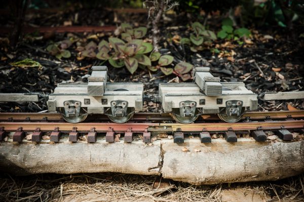
May 21: I started work today on the Hartford Products disconnects or “bobbers” as they are called on some logging outfits. Lots of drilling and distressing of the wood. I’ll use some old Floquil “Natural Pine” stain with a wash of Weather-It. Metal pieces will be darkened with Blacken-It.
May 27: I attended the Memorial Day Weekend Southwest Live Steamers/Houston Area Live Steamers meet at Zube Park in northwest Houston. Photo set available here.
June 10: I finally started back working on the disconnects today, after a few weekends off doing other things.
July 2: We’ve been traveling for a couple of weeks, and when we returned, we discovered the Lost Hollow has become seriously overgrown in several areas. A morning in the garden and things are back in order. I’m also trying to finish up work on the logging disconnects so that I can get back to other projects like some more figures and some buildings.
July 15: I’ve finally completed the logging disconnects to the point where they can be used. I haven’t yet put the brake gear on; it’s pretty fiddly work. Other than that, I’m pretty happy with the way they turned out.
August 20: Once again it’s been a while since I worked on the Lost Hollow; it’s just been too hot here over the last couple of months. However, after our weekly cutting of the lawn, Robin helped me weed the town end of the layout. The forest end has fared much better in terms of weeds. Hopefully, we’ll get a chance to run everything in September. I’m also looking at some more buildings.
Given the Lost Hollow Railway’s logging theme, some log hauling rolling stock would make a good start. Rather than building a simple set of flatcars, I thought I might go for more of a big logging look by getting some disconnects. A single disconnect simply supports the cut tree at one end and relies on the tree to be its own support. Finescale Railroader‘s March 2006 Issue has some excellent pictures of Michigan-California Lumber Company’s disconnects. I especially like the hand-painted car numbers and I will try to do something similar on the Lost Hollow Railway cars.
After doing some Internet searching, I purchased two Hartford Product 1:20.3 narrow gauge logging disconnect kits. The level of detail in the kits is very high and it took me some time to build the four disconnects up. I did leave some of the more fragile parts off the models (brake details mostly) as I was afraid they would not survive the rough handling these models can sometimes get.
In the end, I ‘m very happy with the way the disconnects turned out. They definitely moved some big logs around the Lost Hollow Railway.